Analog Simulation
Analog signal integrity simulations in the time domain are needed to verify the communication between two integrated circuit components. The transmitter (TX) is sending data over the PCB (Printed Circuit Board) and the receiver (RX) is trying to recognize this data. This is an easy task as long signals are slow – but what does “slow” actually mean?
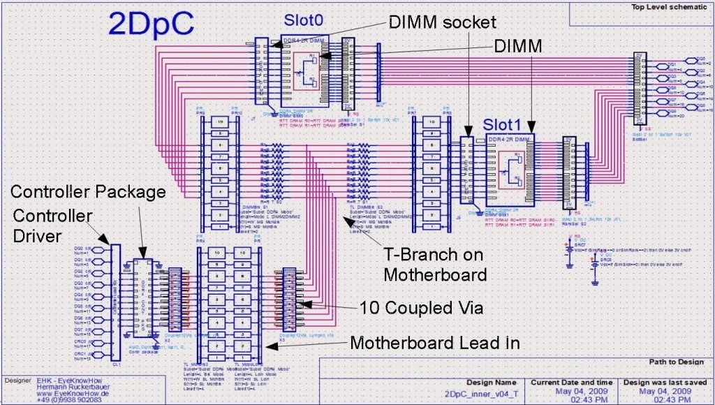
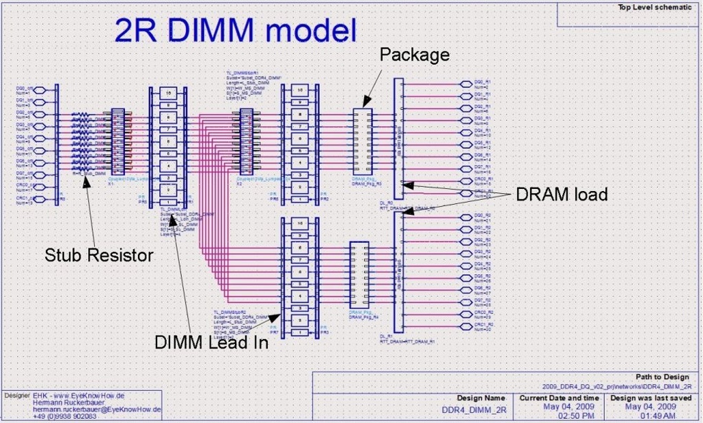
Usually “slow” refers to signals with a rise time being short compared to the physical length of the interconnect. For gigabit data rates there is nothing like a “slow” signal as the interconnect length is always short relative to the rise time. However, it also depends on the topology that is used. If you have a point-multipoint topology, e.g. the CA bus in a memory subsystem, reflections and crosstalk reach a critical level much faster than the rise time rule would indicate.
That’s where an analog simulation is required to verify already in the design phase whether a system will work before it is built. ADS allows to use a schematic-based approach with a very broad library of e.g. transmission line models. An example simulation schematics can be viewed in the gallery at the end of this page.
All kind of different models can be used for such simulations:
- ADS library models (e. g. transmission lines)
- BSIM4 transistor based models
- Spice lumped elements or netlists
- IBIS and IBISAMI models
- S-parameter models (e. g. generated by 2.5D and 3D EM modeling for VNA measurement)
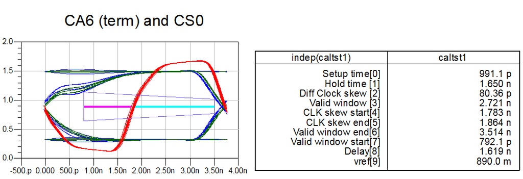
Depending on the simulation target, different simulations can be performed. The most common approach is to simulate a long PRBS (Pseudo Random Bit Stream) pattern on a victim signal and different bit patterns on the neighboring aggressors. Resulting data is post-processed and a data eye is generated. In ADS this is done in the DataDisplay server.
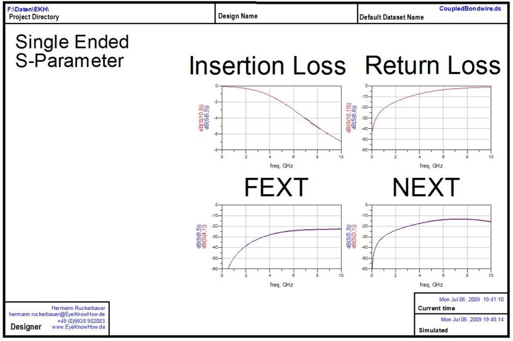
Frequency domain simulations can be performed in this environment too. These simulations allow the characterization and comparison of parasitics for passive components over a wide frequency range. The resulting S-parameter set shows the behavior of Insertion Loss, Return Loss and Cross-Talk.
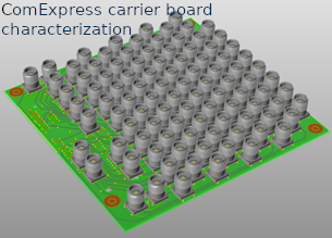
Image Gallery
EyeKnowHow
Hermann Ruckerbauer
Itzlinger Straße 21a
94469 Deggendorf
Germany
Phone: +49 991 29692905
Fax: +49 991 98158793
Mobile: +49 176 78778777
Hermann.Ruckerbauer@EyeKnowHow.de